A L Ict Er Diagram
ER diagrams vs. EER diagrams: What's the difference?

· Jul 26, 2020 · 4 min read

This post was originally published on March 9, 2018, and updated most recently on July 26, 2020.
When designing your database, an entity-relationship diagram (ER or ERD) is an excellent way to visually lay out your plan. So what is EER? In some cases, you may want to opt for an enhanced entity-relationship diagram (EER or EERD), which includes a few more elements than ER diagrams do.
So which one should you choose? When deciding which diagram is best for your project, consider the following.
What is an ER diagram?
An entity-relationship (ER) diagram, also called an entity-relationship model, is aptly named: It shows the relationships between entities. It is most commonly used to organize data within databases or information systems.
There are two kinds of ER diagrams: conceptual and physical. Conceptual diagram models can be used as the foundation for logical data models or to form commonality relationships between ER models as a basis for data-model integration.
Learn the entity-relationship diagram symbol series
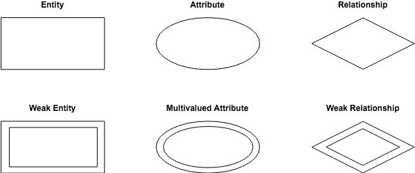
A conceptual ER diagram uses six standard symbols. They are:
- Entities are objects or concepts that represent important data. Also known as strong entities or parent entities, these entities will often have weak entities that depend on them.
- Attributes are characteristics of an entity, i.e. many-to-many or one-to-one.
- Relationships are associations between entities.
- Weak entities depend on another entity.
- Multivalued attributes are attributes that can have more than one value.
- Weak relationships are the connections between a weak entity and its parent.
Physical diagram models are more granular, showing the processes necessary to add information to a database. Rather than using symbols, they are made up of a series of tables.
Each entity is represented as a table with each field acting as an attribute of the entity containing it.
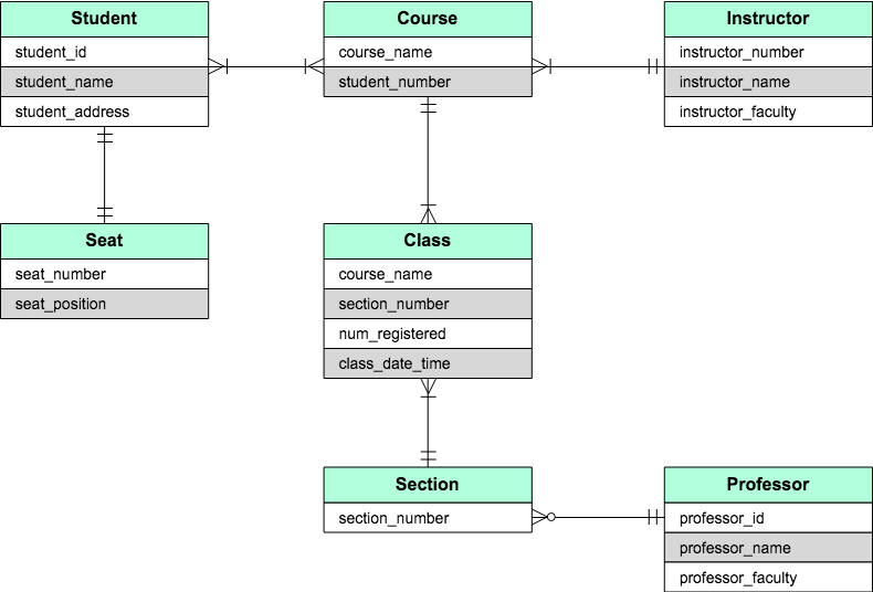
Entities are connected using a system of notation called crow's foot notation. The styling of the endpoint of each line distinguishes the relationship.
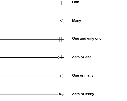
The types of relationships of an ER diagram depend on the interactions the entity has with the other elements. Relationships can be one-to-one (1:1) or one-to-many (1:m). In some instances, the relationship will include many to many (m:m).
What about an entity-relationship model?
"Entity-relationship model" is just another name for the entity-relationship diagram. First coined in the 1970s by MIT professor Peter Chen, "entity-relationship model" was the original working title for the new diagram in his seminal paper "The Entity-Relationship Model: Toward a Unified View of Data." If you see one name or the other while working, don't get confused — they're one in the same.
What is an EER diagram?
Enhanced entity-relationship (EER) diagrams are basically an expanded upon version of ER diagrams. EER models are helpful tools for designing databases with high-level models. With their enhanced features, you can plan databases more thoroughly by delving into the properties and constraints with more precision.
An EER diagram provides you with all the elements of an ER diagram while adding:
- Attribute or relationship inheritances
- Category or union types
- Specialization and generalization
- Subclasses and superclasses
Overall, an EER diagram builds off of an ER diagram by including elements that allow for aggregating, generalizing, and specializing.
Generalization and specialization act as opposites of one another. Generalization combines lower-level entities into one that is a higher level. Meanwhile, specialization divides high-level entities into lower levels. With aggregation, two entities are treated as a single one.
By using the additional components, you can quickly sort and group the relationships within the system for efficient placement.
When to use which
Overall, both diagrams provide the ability to design your database with precision.
An ER diagram gives you the visual outlook of your database. It details the relationships and attributes of its entities, paving the way for smooth database development in the steps ahead.
EER diagrams, on the other hand, are perfect for taking a more detailed look at your information. When your database contains a larger amount of data it is best to turn to an enhanced model to more deeply understand your model.
So when should you use which? Honestly, both are useful, and it depends mostly on the size and detail of your data. The more complicated the data, the more likely you'll need to use an EER diagram to make sure you're properly organizing every relationship.
Both diagrams make designing your database easier than ever. All you need is a great diagramming tool to give you the templates, shapes, and notations you need to create your ER and EER diagrams in a flash.
Collaborate on ideas to align your team's vision in Cacoo
- database design
Cacoo Cacoo is your friendly, neighborhood diagramming app. Since 2009, Cacoo has been helping individuals and teams visualize their ideas with ease. Today, over 2 million users around the world depend on Cacoo to bring their ideas to life.
Source: https://cacoo.com/blog/er-diagrams-vs-eer-diagrams-whats-the-difference/
Posted by: kiaragermone0187727.blogspot.com